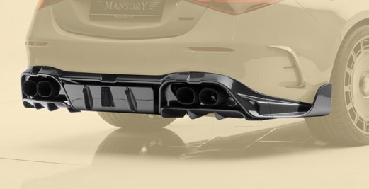
Diffuser with Race brake light Mansory for Mercedes-AMG S63E


Diffuser with Race Brake Light — Carbon Aerodynamic and Signaling Detail for Mercedes-AMG S63e
The rear underbody is a low-pressure region. Air leaving the underfloor decelerates as it expands into the wake; if that expansion is uncontrolled, energy dissipates into turbulence and lift. A diffuser organises the recovery — converting underfloor flow into a coherent pressure-rising channel that pulls the floor downward against the road. The Mansory Diffuser with Race Brake Light performs this aerodynamic role in autoclave-cured carbon construction and overlays a second function: a centrally-mounted high-mount LED race brake light, derived from FIA-style center stop lamps used in endurance and single-seater motorsport. The combined assembly recovers rear-axle pressure and broadcasts a distinctive deceleration signature visible at extended range — a motorsport reference that reads identically by day and by night.
Aerodynamic Architecture
The S63e generates rear-axle downforce through a coordinated chain of rear wing, underbody floor, and rear diffuser. The diffuser is the rearmost element and arguably the most consequential: it controls the rate of pressure recovery between the underfloor and the freestream. The Mansory diffuser uses a tuned geometry built around three coordinated features:
- Venturi tunnels: three primary expansion channels (one central, two outboard) increase in cross-section at a controlled 7–10° angle, allowing underbody flow to decelerate without separation. Transitions are gradual, preserving attached flow at high yaw angles.
- Vertical strakes: four longitudinal fences subdivide the tunnels and inhibit lateral flow migration, maintaining channel pressure under cornering load when sideslip would otherwise allow wheel-arch air to bleed in and collapse the suction.
- Trailing edge geometry: the diffuser exit is sharp and parallel to the road, encouraging clean separation of recovered flow into the wake without re-circulation against the rear bumper.
- Underbody pressure recovery: rear-axle downforce contribution scales with speed squared and reaches approximately 40–60 kg (390–590 N) at 200 km/h.
- Stability under deceleration: the diffuser provides a stabilising aerodynamic moment under braking — exactly the condition where the integrated brake light is illuminated, producing a visual-aerodynamic coherence that is more than coincidence.
LED Race Brake Light System
The race brake light is the defining feature and is engineered to motorsport telemetry standards rather than retrofit aesthetics. It is a centrally-mounted high-mount LED assembly seated in a structural recess in the diffuser upper surface, visible from directly behind the vehicle and from elevated viewpoints. Its electrical and photometric behaviour is governed by deliberate engineering choices:
- Activation logic: the lamp illuminates as a center stop lamp under heavy braking, defined by longitudinal deceleration exceeding 0.7 g read from the OEM ESP/CAN-bus accelerometer feed. Below that threshold the OEM cluster operates normally and the race lamp remains dark — preserving the motorsport signature for the conditions that matter.
- Fog and rain-light mode: a secondary mode mirrors FIA single-seater rain-light protocol — when the rear fog circuit is energised, the race lamp illuminates with a steady beam to maximise rear-conspicuity through aerosol spray.
- Signal sequencing: under heavy braking the lamp can be configured for steady high-intensity output or for a slow pulse pattern (~4 Hz). Pulse mode is firmware-selectable and disabled by default for road use to remain compatible with ECE R48 installation rules.
- Photometric output: approximately 50–80 cd on-axis at rated drive current, distributed across a 90-LED array. Output sits well above the ECE R7 minimum for an S3-class center high-mount stop lamp (25 cd) and well below the maximum (110 cd) that would dazzle following drivers.
- LED array: 90 surface-mount LEDs in a horizontal-vertical matrix on a single PCB, driven by a constant-current regulator that compensates for thermal drift and supply-voltage variation. Individual LED failure does not extinguish the lamp; degraded-mode operation continues until service.
- Optical design: a polycarbonate lens with internal prismatic structure spreads the LED output evenly across all R7 reference angles. There are no hot spots or dark bands, even at oblique viewing.
- Housing: water-tight to IP67 — the assembly survives temporary submersion, high-pressure rain, and pressure-washer cycles. Internal potting eliminates moisture-induced PCB corrosion.
- Thermal management: the array dissipates approximately 8 W at peak output. The aluminium heatsink behind the PCB conducts heat into the carbon laminate; junction temperatures stay below 85°C at 40°C ambient, well within LED life-rating limits.
Regulatory Compliance and Homologation
The race brake light is engineered to satisfy two ECE regulations governing signaling lamps and their installation:
- ECE R7 (signaling lamps): type-approved as an S3-class supplementary stop lamp. Photometric distribution, colorimetry (red, x ≤ 0.660 / y ≥ 0.320), minimum on-axis intensity, and maximum dazzle limits are all validated against R7 test points. The lamp carries the appropriate E-mark on the housing.
- ECE R48 (installation): mounting height, lateral position (centerline ±1°), and visibility geometry comply with R48 for centrally-mounted supplementary stop lamps. The lamp does not displace, occlude, or interfere with the OEM rear lamp cluster — it is supplementary, not a replacement.
- Wiring path: powered via a tap into the OEM brake-light feed behind the rear tail-light cluster, with a CAN-bus interface module that decodes deceleration data from the vehicle gateway. The module is protected against reverse polarity and load-dump transients to OEM EMC standards.
- Type approval: Mansory provides the technical service certificate and ECE type-approval reference numbers on request, supporting registration in jurisdictions that audit retrofit lighting.
Material and Construction
- Outer shell: 2x2 twill carbon fibre at 200 g/m², autoclave-cured at 130°C for full matrix conversion, void content below 1%, and dimensional stability under thermal cycling.
- UV protection: a UV-stable two-component polyurethane clear coat. Validated for 8–10 years of sustained sun exposure in temperate climates without yellowing.
- Finish variants: supplied in visible-carbon (clear-coat over twill, default) or primed (sanded and primer-coated, ready for body-colour paint). Brake-light lens is identical across both.
- Internal reinforcement: unidirectional carbon plies in the strake load paths and around the LED housing aperture, protecting the photometric assembly from flex-induced stress.
- Core material: PVC closed-cell foam in tunnel walls, balsa-wood inserts in high-load zones — impact tolerance without parasitic mass.
- Mass: 4.8–5.4 kg complete with brake-light assembly, fasteners, and harness pigtail.
- Fitment: model-specific to the Mercedes-AMG S63e (W223 generation E-Performance), interfacing with OEM rear-bumper mounting points and rear-harness connector geometry.
Electrical Integration
The wiring tap is the most sensitive part of the installation — incorrect tapping is the most common source of CAN-bus fault codes after retrofit:
- OEM brake-circuit tap: harness terminates in a T-piece spliced into the OEM brake-light feed behind the right-side tail-light cluster. Solder-and-heatshrink, not insulation-displacement, to avoid intermittent contact under thermal cycling.
- CAN-bus pass-through (optional): a CAN interface module with a non-intrusive bus tap reads acceleration data, performs no write operations, and falls back to simple voltage-triggered activation if the CAN signal is unavailable.
- 12V power feed: peak current ~0.7 A (8 W), fused at 3 A inline near the splice to protect the OEM circuit against short-fault propagation.
- Connectors: Deutsch DT-series weatherproof at all junctions — IP67, 100,000+ mating cycles.
Fitment and Installation
- OEM mounting: the diffuser bolts to OEM rear-bumper crash-bar mounting points (six M6 fasteners) plus two supplementary M5 anchors for brake-light alignment.
- Fastener specification: stainless-steel hardware supplied; M6 torque 10 Nm, M5 torque 6 Nm in a cross pattern. Over-torquing will delaminate carbon — torque wrench mandatory.
- Bumper preparation: the OEM bumper requires a small access cut for the harness pass-through (template supplied); the cut is hidden behind the diffuser and is reversible if the part is later removed.
- Functional test sequence:
- Connect the harness; do not yet bolt the diffuser to the bumper.
- With ignition on, depress the brake pedal — verify OEM brake lights illuminate and the race lamp remains dark.
- Switch the rear fog circuit on — verify the race lamp illuminates steadily.
- If CAN-bus integration is enabled, perform a controlled ≥0.7 g brake event — verify race lamp activation.
- Disconnect, install the diffuser fully, reconnect, and re-test.
- Total install time: 2.5–3.5 hours including wiring and functional verification.
Frequently Asked Questions
Q: Will the race brake light cause issues with technical inspection or roadworthiness testing?
A: The lamp is ECE R7 type-approved as an S3-class supplementary stop lamp and complies with ECE R48 installation requirements. It is legal as an auxiliary device on road-registered vehicles in jurisdictions that recognise ECE type approval, and inspection authorities can verify the E-mark on the housing.
Q: Does activating the race lamp disable the OEM brake lights?
A: No. The race lamp is wired in parallel as a supplementary device and does not modify, displace, or de-energise the OEM rear-lamp cluster. OEM brake lights operate normally on every brake pedal application; the race lamp adds a centrally-mounted high-mount channel.
Q: How much rear-axle downforce does the diffuser produce, and at what speeds is it effective?
A: Approximately 40–60 kg at 200 km/h, scaling with the square of vehicle speed. At motorway speed (130 km/h) it is in the 17–25 kg range. The effect becomes meaningful above ~100 km/h and reaches stability-relevant magnitude at sustained high-speed driving.
Q: Can the deceleration-threshold logic be disabled if I prefer the lamp to mirror OEM brakes one-to-one?
A: Yes. The CAN interface module is firmware-configurable; the lamp can be set to follow the OEM brake feed directly, ignoring the deceleration threshold. This mode is selected at installation and remains until reconfigured.
Q: What happens if the CAN-bus interface fails or the gateway changes its signal definition?
A: The interface falls back to simple voltage-triggered activation and behaves as a conventional supplementary stop lamp tied to the OEM brake feed. No diagnostic trouble code is set on the OEM gateway because the interface performs read-only bus operations.
Q: Is the diffuser compatible with OEM rear parking sensors or 360° camera systems?
A: Yes. The diffuser sits below the bumper sensor plane and does not occlude ultrasonic or camera fields of view. Brake-lamp wiring does not interfere with sensor harnesses.
Order the Diffuser with Race Brake Light
WhatsApp +44 7488 818 747 — specification, finish, fitment by VIN
[email protected] — quote, lead-time, freight